| QuickStart | Tutorials | Download | Purchase | Support |
| Reference | ||||||
![]() DHelp helps you learn how to use DirectMesh.
DHelp helps you learn how to use DirectMesh.
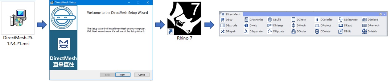
DirectMesh is an intelligent Rhinoceros plugin for efficient mesh and finite element model creation, allowing you to easily build complex finite element models in Rhinoceros' interactive environment. It supports mainstream finite element analysis software such as ABAQUS, ANSYS, FLAC3D, MIDAS, MULTIFRACS, NASTRAN, etc. To use this software, you first need to install Rhinoceros version 7 or above. After running the installer, DirectMesh plugin will be loaded when Rhinoceros starts.
Software Download: Click this link to download DirectMesh
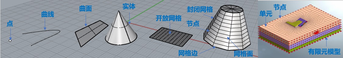
Before using DirectMesh, we need to learn the following concepts: 1. Geometric objects, such as points, point clouds, curves, surfaces, solids, etc.; 2. Mesh, which is a collection of triangular and quadrilateral faces. These faces are called mesh faces, the vertices of mesh faces are called nodes, and the edges of mesh faces are called mesh edges. Meshes are divided into unstructured and structured meshes, with structured meshes being more regular; 3. Finite element model, which is a collection of elements. The vertices of elements are called nodes. Elements are divided into point elements (e.g., concentrated masses), line elements (e.g., beams and columns), surface elements (e.g., shells and membranes), and solid elements (e.g., tetrahedra, pyramids, wedges, and hexahedra, etc.).
The finite element modeling workflow using DirectMesh is: first, create a preliminary mesh from geometric objects, then refine the mesh, and finally build the final finite element model using closed surface meshes representing solid elements, independent meshes representing surface elements, polylines representing lines, and points representing point elements. The details are as follows:
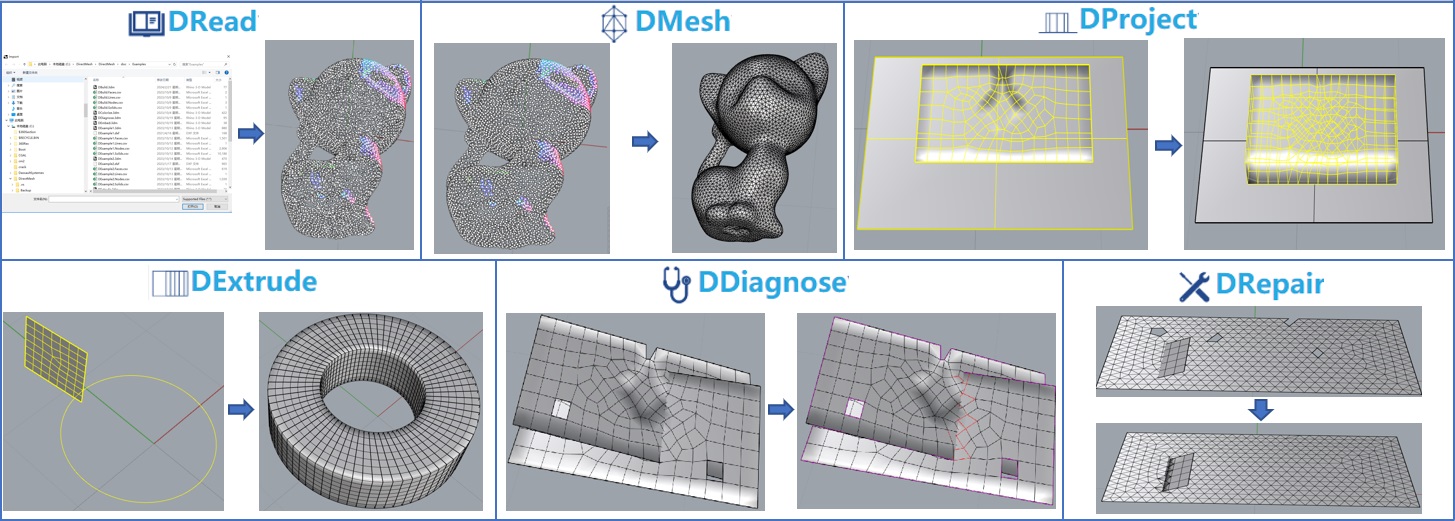
Step 1: Create preliminary mesh models from various geometric models. The DRead command can load various geometric models. The DMesh command can create preliminary mesh models from geometric models (e.g., generating corresponding meshes from solids or point clouds). The DExtrude command can extrude a mesh along a curve to form a closed mesh (e.g., extruding a tunnel cross-section mesh along the tunnel axis to create a mesh model representing the tunnel). The DProject command can project a table onto a surface and generate the corresponding closed mesh (e.g., projecting a mesh representing the soil surface onto a plane and generating the corresponding mesh model). The DDiagnose command can diagnose conflicting faces, holes, and collinear situations in a mesh. The DRepair command can automatically fix errors in the mesh (e.g., repairing conflicting faces, holes, cracks, protrusions, duplicate identical or adjacent nodes, non-coplanar quadrilateral mesh faces, etc. It can also merge two triangular mesh faces sharing an edge and being coplanar into a quadrilateral mesh face).
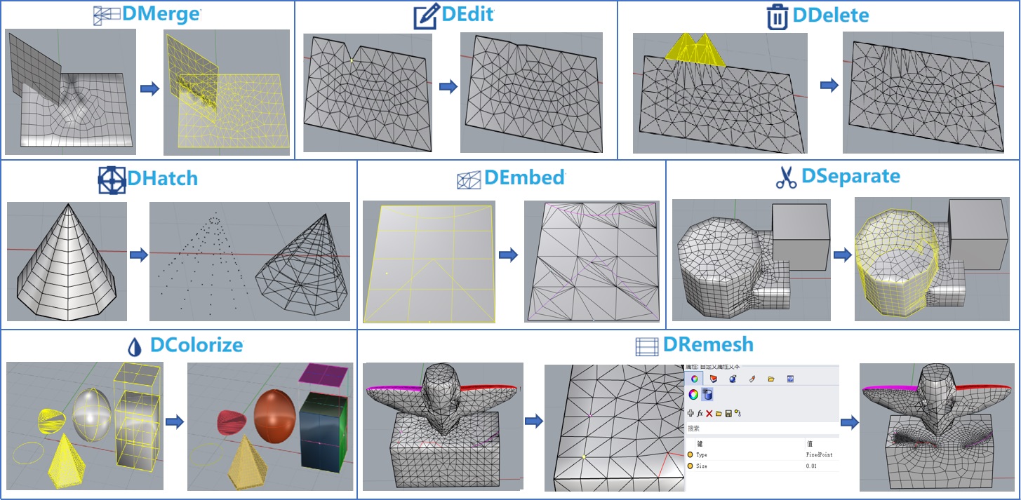
Step 2: Refine the mesh model. The DMerge command can merge multiple meshes and curves with shared nodes (meshes representing multiple structures that are embedded in each other but not node-shared generally lead to finite element analysis failure, and this command can solve this problem). The DEdit command can edit the positions of nodes in a mesh. The DDelete command can delete unnecessary mesh faces. The DHatch command can extract all nodes of a mesh and generate a point cloud, extract mesh edges as a skeleton, or generate boundary edges of a mesh. The DEmbed command can embed polylines into a mesh with shared nodes (e.g., embedding polylines representing rails into a mesh representing the ground). The DSeparate command can split a mesh based on a breaking angle and other criteria (this function can partition the mesh, facilitating the addition of boundary conditions and load conditions in the final finite element model). The DColorize command can randomly color meshes and various geometric models for easier distinction. Finally, the DRemesh command can be used to perform high-quality remeshing (controlling overall size and local size in certain areas, preserving fixed points, fixed edges, and fixed mesh faces, supporting both structured and unstructured meshes).
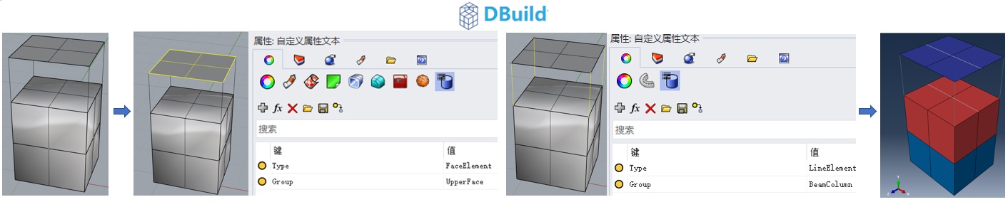
Step 3: Use the DBuild command to generate the final finite element model input file, which will also output the corresponding finite element model in Rhinoceros. It supports mainstream finite element analysis software such as ABAQUS, ANSYS, FLAC3D, MIDAS, MULTIFRACS, NASTRAN, etc., supporting solid elements, surface elements, line elements, and point elements. Closed meshes will automatically generate corresponding solid elements. Adding a user-defined property Type=FaceElement to a mesh will generate corresponding surface elements. Adding a user-defined property Type=LineElement to a polyline will generate corresponding line elements. Adding a user-defined property Type=PointElement to a point will generate corresponding point elements. The output finite element model will retain all element grouping information. Then, you can load the corresponding model in commercial finite element software and perform finite element analysis.
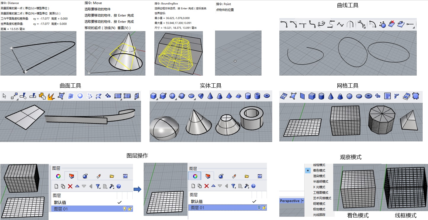
For more flexible and efficient modeling, you also need to master the basic usage of Rhinoceros appropriately, such as the Distance command to measure the distance between two points, the Move command to move geometric objects, the BoundingBox command to generate the tightest bounding box of a geometric object, the Point command to generate specified points, curve tools to generate various curves, surface tools to generate various surfaces, solid tools to generate various solids or perform Boolean operations on solids, etc. Additionally, you need to learn the layer operations provided by Rhinoceros, such as showing, hiding, locking, unlocking, etc. Changing the view mode (e.g., wireframe, shaded, rendered, etc.) can help you better visualize the model.
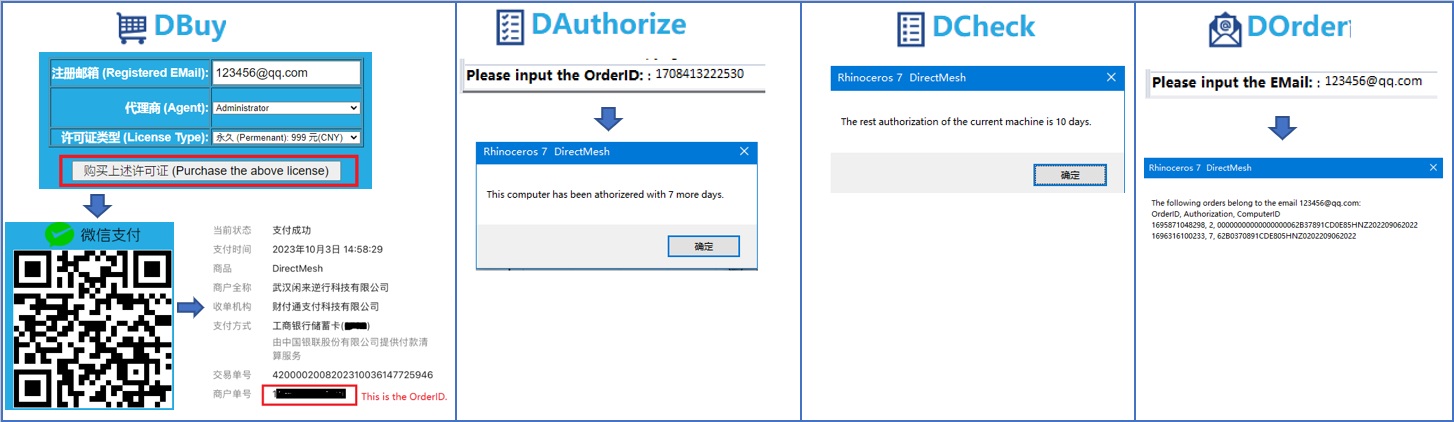
Upon first use, DirectMesh will automatically bind to the computer and can be used free for 14 days. After that, users need to purchase a license via WeChat Pay to continue using it. You can purchase a license using the DBuy command. The WeChat payment order number is the license. Then you can use the DAuthorize command to bind the license to your computer. The DCheck command can check the remaining usage time on the current computer. The DOrder command can view all licenses associated with the user's registered email.
License Purchase: Click this link to purchase DirectMesh license
For questions, please contact Dr. Xu, Phone: +86-15927279709, QQ: 2650616297, QQ Group: 745410771.